August, this year, was a month of full relax. No progress on the boat.
When back to work in september I was faced with a slow progression for two reasons.
First a lot of "invisible" details. Little things that had been left behind and now needed to be completed.
The aim is to be able to apply the insulation at the beginning of november.
I choose to spray the Dunapol-S 235. I will come back to discuss this choice when it will be time.
The fact is that in this case no more welding will be possible,on both sides, on surfaces that are insulated.
As a consequence a series of little pieces (reinforcement counterplates for the bollards, chainplates, watertightness of bulkheads.......) need to be completed.
Second the placement of the rudder and steering system.
This piece of equipment is the last to require a lot of attention to alignment, distortion, distances etcetera.
The steering system I have chosen if the Jefa rack and pinion. The choice was based on the evident superiority of this type of system in terms of strength and easyness of maintenance.
I also decided to install two Jefa electric actuators for the autopilot (one spare).
A LOT OF ACCURATE WORK!
Helsman'Seat
The first step was to open two accesses on the helsman's seat to be able to enter the lazarette where the rudder shaft will be placed.
Here you have an idea of where the steering wheele will be placed.
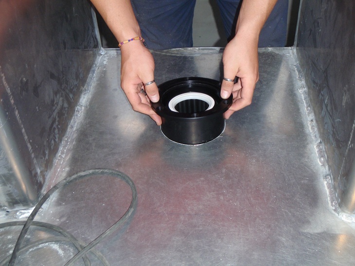
The rudder bearing from Jefa is shown in the figure below. On one side, the bottom it has a Delrin ring to protect it from debris coming from the water. On the top is the spring that when removed will allow to extract the bearing from below. The bearing can be tilted vertically, in this case the spring will be released from below and the bearing extracted from above. Probably ten years from now! At least so we hope.
Here you see the spring removed
The sphere containing the bearing can be rotated and removed.
All this disassembling is necessary as the bearing will be welded to the hull and the reinforcements.
The opening in the 10mm hull reinforcement must be enlarged to 180mm
Then the point on the deck for placement of the upper bearing must be identified.
Now the bearing will be prepared for welding removing the anodization from top and bottom part. As a matter of fact it we should had ordered the "weld in" option but we did not get it.
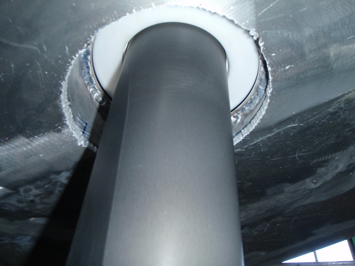
Now the bearing must be placed vertical while the hull is not.
So we used a section of 200x20mm 5083 pipe cut obliqually to obtain the horizontal surface.
On this we placed an anular platform to supprot the bearing.
Now we ha to position it and check with the laser.
Ant finally tack weld in place.
Now we move our attention to the upper bearing.
Now everithing is ready for testing the rudder shaft alignment.
Luckily every fitted perfectly!
Now we had still two problem to solve.
One is the fact that the upper bearing was protruding 2 cm above the flat surface in a position that will probably be hit by barefeet several times a day. We wanted it flash to the bridge.
Second the reinforcement for both bearings.
This is what we did for the upper one.
And according to Jefa instructions for the bottom one.
Now the steering mechanism. One important point in evaluating how well a boat is built is to grab the pedestal and with your weight see if it mooves. If it moves it is bad construction.
The draglink connecting the rudder shaft to the wheel pinion goes through the watertight bulkhead.
So box that works both as a support for the pedestal base and as extension fro the watertight bulkhead need to be constructed.
Of course it need an inspection panel.
Now the basement for the pedestal is placed and will be welded to the watertight-reinforcement box.
Finally the opening on the bulkhead for the draglink.
E voila! The boat has the steering!